|
A study of LC alignment on variously prepared substrates shows that the anisotropy in the surface roughness of the substrate completely determines the direction of LC alignment. It has been known for a long time that rubbed polymer films, Langmuir-Blodgett(LB) films, vacuum deposited dielectric layers, polymer films exposed to linearly polarized ultraviolet (LPUV) light, photoaligned liquid crystal (LC) , and other methods which produce a grooved surface induce alignment of LCs. The results of our high resolution x-ray reflectivity (HRXR) measurements on various substrates prepared by different processes establish that the anisotropy in the roughness of the substrate’s surface determines the direction of LC alignment. In all the cases studied, including those where an anchoring transition occurs with temperature, the LC director (re) aligns in the directions of low roughness. |
|
3. Characterizations of LC Alignment Surfaces Using X-Ray Reflectivity |
|
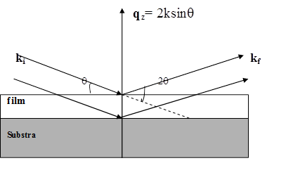
XRR is one of the most powerful and widely used nondestructive tools to investigate the surface morphology of thin films prepared by various methods. This method involves measuring intensity as a function of x-ray incident angle. X-rays impinging on a solid surface undergo total external reflection if the angle of incidence is smaller than the critical angle. At angles of incidence larger than the critical angle, x-rays begin to penetrate the surface and the reflectance drops rapidly in a manner similar to the Fresnel reflectivity in the visible regime. The Kiessig fringes are generated by the interference between the x -rays partially reflected from the air-film and from film-substrate interfaces. The amplitude of fringes diminishes with increasing surface roughness averaged over the coherence area of the x-ray beam. The small angle x-ray geometry is shown in fig. below. The incident x-rays impinge on the sample at a small angle θ and the reflected intensity of x-rays is detected at an angle θ from the surface; the scattering angle is 2θ and the scattering vector q is normal to the scattering plane and are collected as function of θ or equivalently qz = 2ksinq where wave vector, k = 2p/l The interference of x-rays reflected by the air/film and film/substrate interfaces gives rise to a series of pronounced maxima and minima (Kiessig oscillations) shown in figure below. |
|
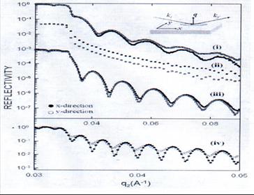
X-ray reflectivity profile for x(•) and y(°) directions, in the scattering plane(inset) ,for (i) rubbed PVA,(ii)Rubbed glass(iii) LPUV exposed LPP, and (iv) rubbed PI films. |
|
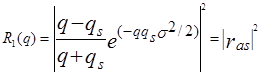
The spacing ∆qz between the minima (or maxima) is a direct measure of the layer thickness. From the fringe spacing, the layer thickness d and the mean electron density along the surface normal can be easily determined. The roughness of real surfaces is traditionally modeled using a Gaussian distribution of surface points resulting in attenuation of the reflectivity by a Debye-Waller-like factor exp(-q2σ2), σ being the rms roughness. The specular reflectivity R(q) of x-rays from a single (air/substrate) interface can be described by the Fresnel formula multiplied by a Debye-Waller-like factor as: |
|
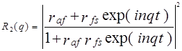
Where q and qs are the magnitude of the x-ray momentum transfer vectors in air and the substrate, respectively and for a film of thickness t and x-ray refractive index n deposited on the substrate, the reflectivity of x-rays can be written as |
|
Where The determination of the anisotropy in a film’s morphology by HRXR is made possible by inherent unequal x-ray coherence lengths of ~5000Å and ~60Å in directions longitudinal and transverse to the direction of incidence, respectively. Specular reflectivity scans are conducted in two different orientations of the sample i.e. along x, the direction of treatment (i.e. rubbing /direction of UV polarization) and y perpendicular to it which is obtained by 90o rotations about the scattering vector, q perpendicular to the substrate. The reflectivites along x and y will be different if the substrate’s surface is anisotropic which we measure in terms of σ value. |
Selected Publications1. What aligns liquid crystals on solid substrates? The role of surface roughness anisotropy, S. Kumar, J.H. Kim, Y. Shi, Phys. Rev. Lett. 95, 077803 (2005). 2. Three Dimensional Orientational Ordering in the Bulk and on the Surface of the Polymer Substrate and their Effect on LC Alignment, O. Yaroshchuk, Yu. Zakrevskyy, J. Kelly, S. Kumar, L.-C. Chien, and J. Lindau, Phys. Rev. E69, 011702 (2004). 3. Isothermal Relaxation of Rubbed Polystyrene Thin Films Probed with Optical Birefringence Measurements, A. D. Schwab, B. Acharya, S. Kumar, and A. Dhinojwala, Modern Phys. Lett. B 16, 415 (2002). 4. Wetting-Dewetting Transition and Conformal to Non-Conformal Interfacial Roughness Transition in Ultra-thin Liquid Crystal Films on Substrates, K. A. Suresh, Y. Shi, A. Bhattacharyya, and S. Kumar, Mod. Phys. Lett. 15, 225 (2001). 5. Chain Orientation and its Effect on Mobility at a Rubbed Surface, Y. Pu, H. White, M.R. Rafailovich, J. Sokolov, S. A. Swarz, A. Dhinojwala, D.-M. G. Agra, and S. Kumar, Macromolecules 34, 4972 (2001). 6. Anisotropic Surface Morphology of Azopolymer Films Generated by Polarized UV Light Irradiation, O. Yaroshchuk, Dena Mae G. Agra, Y. Zakrevskyy, L.-C. Chien, J. Lindau, and S. Kumar, Liq. Cryst. 28, 703 (2001).
|